
Turning a flat sheet into a working assembly involves more than sending a DXF file to the fabrication floor. Material grade, thickness, bend sequence, hole locations, dimensional allowances and mating features all influence whether the first physical prototype behaves as intended.
Engineers preparing prototype sheet metal fabrication drawings can reduce avoidable revisions by considering how each specification translates into cutting, forming and assembly operations. At Hanstar Technologies, we view the drawing as a manufacturing document as much as a design reference, so practical fabrication constraints need to be visible before production begins.
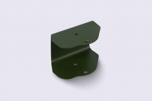
Define Material Before Building The Flat Pattern
Material selection affects both forming behavior and finished-part performance. Aluminum may suit applications where low weight matters, while stainless steel can be considered for environments requiring corrosion resistance or greater durability. Carbon steel offers another option for structural applications where stiffness and cost need to be balanced. Material thickness should be stated clearly because it affects bend geometry, rigidity and the developed flat pattern.
Bend allowances deserve equal attention. The neutral axis does not sit at the exact center of every bend, and its position can vary with material, thickness, tooling and bend radius. Using a generic allowance across different materials may produce discrepancies between the CAD flat pattern and the fabricated component.
Engineers should also specify the inside bend radius where it has functional significance. Tight bends can affect material integrity or create forming limitations, while larger radii may influence available space inside an assembly. During custom sheet metal fabrication services, these parameters can be reviewed together rather than treating the flat pattern as an isolated geometry.
Connect Tolerances With Assembly Interfaces
Not every dimension requires the same level of precision. Tight tolerances make sense around locating holes, bearing seats, mating surfaces or interfaces that affect assembly alignment, whereas cosmetic or non-functional edges may accommodate wider variation. Assigning tolerances according to function keeps drawings technically meaningful without placing unnecessary demands on every feature.
Hole-to-bend relationships deserve particular care. A hole positioned too close to a bend can be affected by deformation or may interfere with forming tools. Slots, tabs and interlocking features should likewise be evaluated according to how the part will be formed and subsequently assembled.
The assembly itself provides useful context for tolerance decisions. If two panels must align with fasteners, the drawing should communicate which features establish location and which merely provide clearance. Engineers preparing prototype sheet metal fabrication packages can also identify critical interfaces separately so inspection focuses attention where dimensional variation has the greatest functional effect.
Prepare Finishing Requirements Alongside Geometry
Surface treatment should not be left as an undefined note at the end of the drawing. Powder coating, anodizing, plating, brushing or other finishes can change appearance, surface dimensions and the way components interact with fasteners or mating parts. The specification should state the required finish and identify areas where treatment needs to be limited or avoided.
Edges and formed features may require additional consideration after cutting. Laser-cut profiles can have characteristics that differ from formed surfaces, while small holes and narrow slots may respond differently from larger openings. The intended visual and functional result should guide how these details are documented.
Finish requirements also belong in the prototype validation plan. A bare-metal prototype may confirm fit and geometry, yet a finished sample can reveal changes in appearance, coating buildup or assembly clearance. Incorporating these factors into custom sheet metal fabrication services makes the prototype more representative of the eventual application.
Build A Practical Drawing Checklist
Before releasing fabrication drawings, engineers can verify several fundamental items: material grade, sheet thickness, grain direction where relevant, bend radius, bend allowance method, hole and slot dimensions, critical tolerances, datum references, surface finish and inspection requirements. Assembly drawings should also show the relationship between fabricated parts and any components they must accommodate.
File consistency matters too. The 3D model, flat pattern and 2D drawing should describe the same revision. Conflicting dimensions or outdated geometry can create unnecessary clarification cycles, particularly once several components are being developed together.
The final review should ask a functional question rather than simply checking whether every field has been filled in: can another engineer understand how this part is expected to be cut, formed, finished and assembled? A clear drawing package gives fabrication teams enough information to work from while leaving room for appropriate manufacturing feedback.
Connect Prototyping With Production Readiness
Prototype work becomes more valuable when the first sample provides information about future production rather than merely proving that the geometry can be fabricated. Engineers can record actual bend results, assembly clearances, finishing effects and dimensional observations, then use those findings to refine subsequent revisions. This feedback makes the transition from prototype to repeat production more evidence-based.
Our precision sheet metal fabrication capabilities at Hanstar Technologies include fiber laser cutting, bending precision of ±0.1 mm, and support for programs ranging from prototypes to volume production. Quality control is incorporated into the fabrication workflow so dimensional requirements can be checked against the applicable drawing specifications.
Conclusion
Flat-pattern accuracy is only one part of prototype readiness. Material behavior sets the foundation, bend allowances translate three-dimensional form into developed geometry, tolerances define functional relationships, and finishing requirements shape the final interface. Once those elements are documented clearly, the prototype can serve as a meaningful test of both design intent and assembly performance.
We at Hanstar Technologies support prototype sheet metal fabrication and related engineering requirements with cutting, precision bending, quality control and scalable production capabilities. Share your fabrication drawings and assembly requirements with our team to discuss the next stage of your project.